- For secure high-pressure
- +36 62 999 051
- info@pwent.eu
Termékek
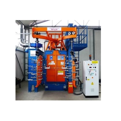
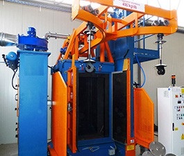
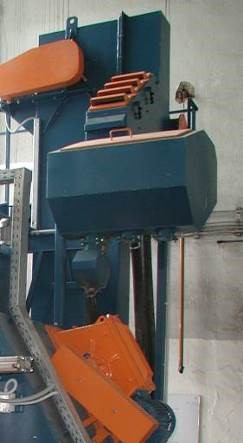

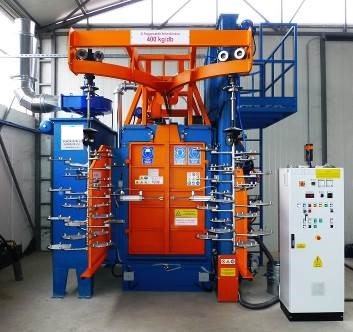

HC-800-2-shoot blasting machine for gascylinders
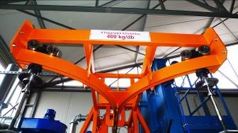
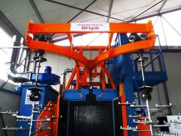
3 turbine shoot blasting machine with Y conveying line for gascylinders outer cleaning
Gas cylinder length -1200 mm, diameter -800 mm, weight -400 kg, 2 impeller wheel turbine shoot blasting machine for gascylinder outside cleaning. HC-800-2 blasting chamber type, hand operated overhead conveyor, charge shot-blasting machine. 500 kg shoot load capacity, 6-12 hangers/hour (250 pc cylinder/shift). According to the gascylinder size one hanger could mean more gascylinder as well.
Options
- ATEX filter and safety fulfillment
- Turbine variable RPM by frequency regulator
- Installation and first start is charged separately
Technical description
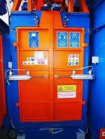
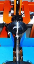
The HC 800 type shot-blasting equipment is generally offered for the surface cleaning of smaller castings, welded work-pieces, parts which can be suspended in bunches. The machine has two blasting turbines. Their shifted position ensures the cleaning effect of the blasting jet on the whole surface of the work-pieces. The shot-blasting material is led to the turbines axial gravitationally. The turbines are 6- blade constructions, with pre-acceleration, with accurate blasting jet adjustment opportunity. The parts to be blasted are dragged into the cleaning chamber manually on a conveyor path hook. The hook, together with the work-pieces, performs continuous gyratory movement at one, two or three places, or it performs continuous movement in front of the blasting wheels – depending on the construction. The two hooks mounted on the ‘Y’ path makes it possible that while one of the hooks is in the blasting cabin, the next batch can be prepared for blasting on the other one. In case of basic execution, the hooks must be dragged to the door of the blasting cabin manually. The machine has a hook pulling mechanism which moves the hook into the blasting position inside the machine house. After finishing blasting, it pushes it back to the door, from where it must be pulled to the take-off position manually again. We can also supply the equipment with hooks lifted and moved mechanically. The inner surfaces of the blasting cabin in the active zone are covered with highly wear-resistant manganese steel, other inner parts are protected by wear-resistant rubber sheet. Shot-blasting can only be done with the doors of the cabin closed. It gives perfect protection against the shots shooting out. The doors of the cabin are opened and closed by a pneumatic cylinder. The closed and continuous circulation of the shot-blasting material is ensured by the screw conveyor, bucket elevator, abrasive cleaning unit and the feeding unit. For optimal surface cleanliness, the amount of the blasting material and the blasting time can be infinitely variable. As an optional item, the number of revolutions of the blasting turbines can be adjusted by a frequency converter. After finishing the blasting and opening the door, the cleaned parts must be taken out of the chamber manually and changed for the next hook with new parts prepared for blasting. The dust created during shot-blasting is aspirated and separated with the help of modern, cartridge system dust aspirating-separating equipment. The equipment can be controlled from the central control box. Manual mode of operation is possible for service purposes, for normal operation mode automatic mode is available.
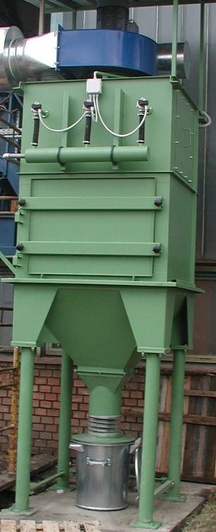
Technical description of the APSZ cartridge dust-separator
The aim of the equipment – The equipment is used for filtering the dusty air generated in industrial factories. It is fully automatic and ensures the separation of different kinds of dust with high efficiency.
The operation of the equipment – The air (gas) to be cleaned flows into the air chamber. It flows through the filter cartridges from the outside to the inside and in the meantime the dust is separated at the outer surface of the cartridges. The clean air leaves through the discharge chunk, the separated dust falls into a hopper and then it leaves the filter through the outlet. The cartridges are cleaned by blowing in compressed air. The time span of the blowing-in and that of the break can be changed by means of the electronic control unit.
Constructional description – The equipment is manufactured on the „building cabinet” principle. The filter elements and certain parts of the frame and the control is the same in case of different size dust filters. The air to be cleaned enters the machine through the chunk on its side. The air flows through the cartridges, enters the outlet chamber, and then leaves the equipment through the suction cover. The air can get into the outlet chamber only through the filter cartridges. The back wall of the outlet chamber has a special design in order to hold the cartridges properly. The filter cartridges are fixed with screws. The blowing pipes for cleaning the cartridges are placed in the outlet chamber. They are placed in such a way that the high pressure air coming from the bores can flow into the cartridges to blow the accumulated dust off the surface of the filter cartridges. The air from the air tank gets into the blowing pipes through a membrane valve. The membrane valve is controlled by the electronic control unit. The time span of the blow-off and that of the break can be adjusted. There are large sealed doors on the outlet chamber for changing the filter cartridges and making the maintenance safe. The dust falls into the hopper under the chambers and from there it gets into a dust-collecting vessel through the dust discharger. The quality of the cartridges built into the equipment and the measurements done so far ensure that the dust emission after the filter is not more than 3 mg/m3, so the clean air can be led back. The inlet and outlet chambers of the machine are made of steel plate. The sealing between the elements prevents dusting out. The machine is mounted in a profile steel frame and can be fixed through the frame elements. The equipment does not need any maintenance. The lifetime of the cartridges is about 3.000 working hours.
Delivery units
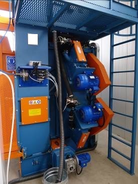
Machine housing is a welded construction with steel profile frame elements. The inner surface is protected with high manganese content replaceable steel cover plates. There are three pieces of ABR-D400 direct driven turbines mounted on the side of the housing. Each turbine has an electric motor with 7,5 kW electrical power and 2940 1/min maximal revolution speed. The machine house is on four stands. The bottom of the machine has a conical chape hopper to collect the abrasive media with the help of a screw conveyor. This conveyor proceeds the shot blasting material to the bucket elevator. On the top of the machine housing the conveyor rotation driving is situated. For the aspiration of the dust created during shot-blasting there is a suction outlet on the side of the housing to be connected to the aspiration system.
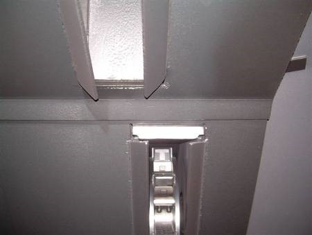
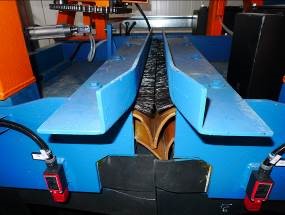
Manganese wear protection The whole inner surface of the machine housing is covered with high manganese content steel wear resistant plates. The thicknesses of the plates are 5-8 mm. Wear protection provides long lifetime for the structural units of the machine against the harmful abrasion caused by the blasting stream.
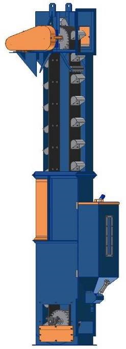
Bucket elevator The main parts of the elevator: lower housing, upper housing, elevator head. The lower housing contains the lower drum with bearings and bearing housing. This housing is bended plate construction that is assembled by welding. On the side connecting frames are situated to be bolted to the screw conveyor. The upper housing is a simple rectangle cross-section self-holding structure. The service door is located on it as well. The head provides elevator driving. It has an upper driven drum, chain straining system, drive and an unloading outlet. The head is mounted on the upper housing by bolt connections. In the head the driving drum leads the rubber belt with the buckets. The belt straining is also being done by drum adjustment. The gear drive is connected to the drum via chain transmission. The buckets are fixed on the infinite textile composite rubber belt by bolt connections.
Elevator capacity: 6 m3/h
Driving power: 2,2 kW
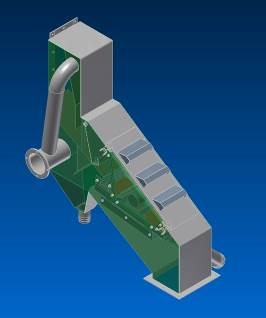
Abrasive cleaner unit This unit is made for cleaning the shot blasting media by two steps suction system. The air classifiers each cleaning step is covered by rubber protection. On the service door the suction inlets are situated. On the back side of the unit the outlet tube is mounted with connection flange to be ducted together with the aspiration system. The air velocity can be adjusted by butterfly valves at the outlet section of the air classifier. The dust separated in the classifier leaves the unit and is being collected in the dust container. The cleaned blasting media flows towards to the abrasive dosing tank.
Abrasive dosing tank The cleaned abrasive media is collected in a dosing tank. The tank has three connection pipes on the bottom. These pipes are mounted with pneumatic sector valves to provide the precise adjustment of shot blasting material flow. The abrasive flow can be set up by adjusting the bumpers on the sector valves. Blasting media entering the tank has to flow through a sieve to avoid from bigger alien parts (bolts, nuts, etc.) getting into the blasting turbines. The steel shot gets to the turbines via wear resistant rubber hoses.
Tank volume: 0,5 m3
Blasting material outlets: 3 pieces
Dust aspiration system
- 1 piece APSZ 6 cartridge filter with automatic compressed air REVERSE JET cleaning system (complete with control system, cartridges, ducts, dust hopper, stands)
- 1 piece dust containe
- Radial fan with electric motor
- Air ducting with all necessary valves, noise reducer and fastener
Technical details:
- Air flow rate: 5200 m3/h
- Nominal working temperature: 20 °C
- Number of cartridges: 6 pieces
- Filtering area: 126 m2
- Compressed air demand: 10m3/h – 6 bar
- Fan electrical power: 5,5 kW
- Total pressure drop: 2500 Pa
- Dust emission: 3 mg/m3
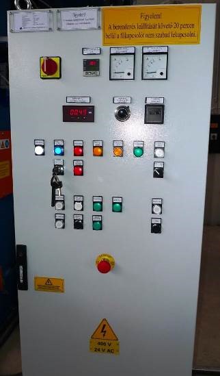
Control All electrical equipment can be started and stopped from the control box. Here is situated the main power switch. With this the machine can be supplied with electricity and the electrical power can be shut off. The blasting positions and the blasting time intervals can be programmed with the control box. The control provides the right order starting of the electric motors and the turning off automatically. It is equipped with safety relays and protection against overloading.
Technical details:
Electrical supply: 3 x 400 V
50 Hz
Control voltage: 24 V AC
Optional units
Motorized hook movement and crane lifting (up to max. 2 tons) In this case the path is assembled with two electric movement and lifting cranes. These cranes let the heavier work pieces to be blast cleaned without hard work of hanging the pieces by hands.
The lifting and moving mechanism is built form standard crane and hoist elements. In the case of a “Y” path a pneumatically controlled path shifter mechanism helps to use the desired crane.
Frequency regulator for blasting turbines With changing the revolution speed of shot-blasting turbines, different shot velocities can be reached. This equipment helps to precisely adjust blasted surface properties. In the range of 2300-2940 rpm (effective blasting rpm range) with the control box a suitable blasting process can be set up for every kind of cleaning tasks.
Assembling, mounting and starting up The delivered machine parts are mounted together by our professional technical staff. They start up the machine and they give an education of operation and maintenance to the buyer’s personnel. Our technicians make every necessary measurements of electrical safe and they write a report of it. We provide all documentation is needed to operate and maintain the machine.
Technical details
The hanger technical parameters:
- Max height: 1200 mm
- Max diameter 1200 mm
- Max weight 400 kg
- Material to be blasted: steel
The dimensioons of the shoot blasting machine and necessary space to install: accorting to the attached drawing
Blasting method: with impeller wheel manual or automatic method
Necessary staff: 1 person
Blasting material: Steel shoot GP type
Blasting material load: 500 kg
Blasting performance: 6-12 hanger/hour
The noise level of the machine: 79-83 dB(A)
Turbines
Number of turbines: 2 pc
Type: ABRD-380
Diameter: 380 mm
Rotation of the turbines: 2600 turn/minute
Scattering power: 90 kg/min/turbine
Electrical power:: 5,5 kW/turbine
Conveyor line
Maximum load: 400 kg/hanger
Consumption
Electrical: 16,5 kW
Compressed air
Pressure: 6 bar
Quantity: 6 m3/hour
Dust separator ventillator power: 3500 m3/h
Electrical data
Voltage: 3 x 400 V
Controlling voltageVezérlőfeszültség: 24 V
Frecvency: 50 Hz
Related products
- Ajánlatkérés
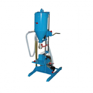
TOTEM TS-equipment for powder extinguisher filling emptying
3 530,00 €The “TOTEM-MTS” is specifically designed for extinguishing powder filling and emptying operations at fixed extinguishing systems.
- Read more
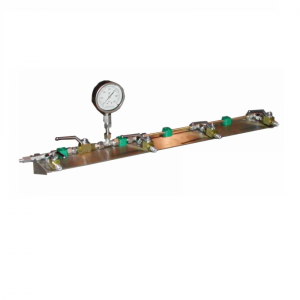
HT model- wall mounted hydraulic ramp for high pressure cylinder testing
Price range: 340,00 € through 470,00 €The ramp is specifically designed to achieve the testing of cylinders / reservoirs safely and efficiently
- Ajánlatkérés
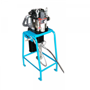
N7/4 model Pneumatic pump for hydraulic pressure testing
Pneumatically driven, N7/4 pump allows to easily set the required pressure.
- Ajánlatkérés
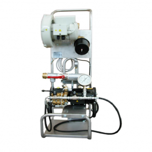
N7/1FH-EAA-portable electric testing pump for extinguishers
2 820,00 €Easily adaptable to different testing needs, this flexible pump does not need any compressed air for its functioning