- For secure high-pressure
- +36 62 999 051
- info@pwent.eu
Termékek
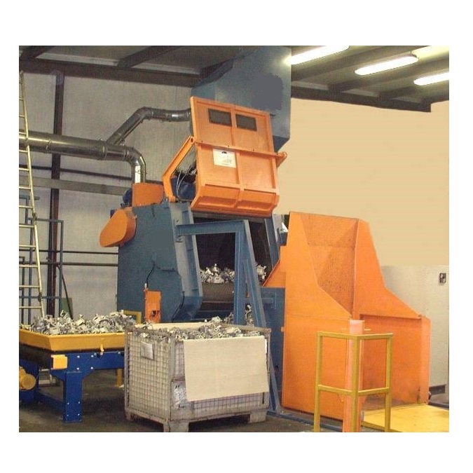
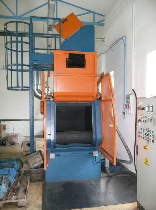


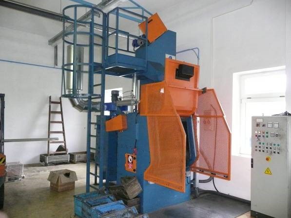
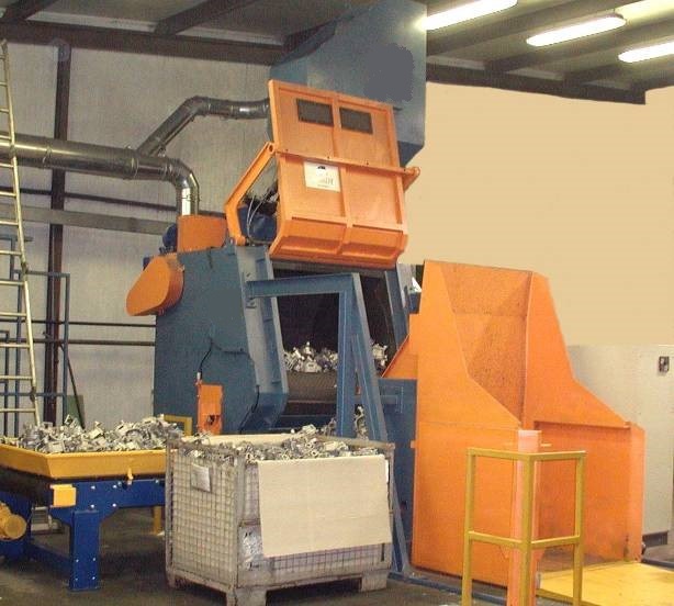
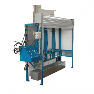
GH2 rubber belt shot blasting machine
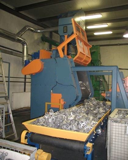
950 mm wide rubber belt shot blasting machine with 900 mm diameter. Max batch 400 kg, 7 kg each. Caps, speare parts cleaning.
950 mm wide rubber belt shot blasting machine with 900 mm diameter. Max batch 400 kg, 7 kg each. Caps, speare parts cleaning. We offer the GH 2 type shot-blasting equipment for the bulk surface cleaning, surface treatment of cast, wrought, pressed parts.
Options for rubber belt shot blasting machine
- Automatic hydraulic feeding equipment
- Discharge conveyor belt
- Electronic rotational speed control of blasting wheel
- Electronic speed control of rubber belt
- Magnetic separator for removing forming sand
As an optional item we can deliver automatic hydraulic feeding equipment for the rubber belt shot blasting machine, which feeds the prepared work-piece batch into the equipment. To reach the optimal surface cleanliness, you can set the amount of the blasting material and the blasting time. As an optional we could add a frequency converter to the turbine. With the frequency converter and with the changing the revolution number of the blasting turbine, you can increase or decrease the impact speed of the shots.
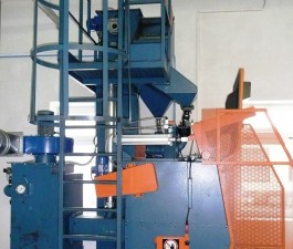
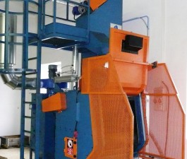
Installation layout:
Rubber belt shot blasting machine – Technical description
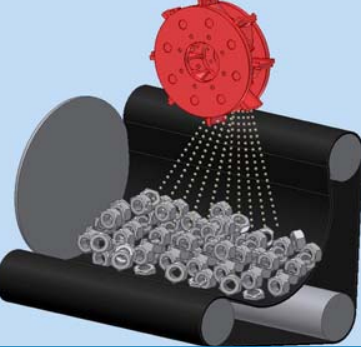
We offer the GH2 type shot-blasting equipmentfor bulk surface cleaning. You can make surface treatment of cast, wrought, pressed parts. The equipment has got one piece of blasting turbine. The machine’s turbine axial lead the shot-blasting material gravitationally. The turbines has 6- blade with pre-acceleration and with accurate blasting jet adjustment opportunity.
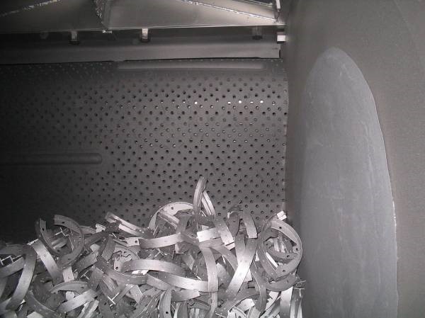
Working
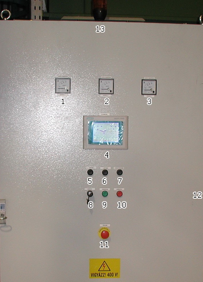
Place the parts on the rubber belt through the door on the front of the machine. With the rotation of the rubber belt, the work-pieces in the machine house move on each other while the shots thrown from the turbine clean their whole surface. We covered the inner surface of the blasting cabin with highly wear-resistant manganese steel. The machie works if the doors of the cabin closed. It gives perfect protection against the shots shooting out. The bucket elevator and abrasive cleaning unit and the feeding unit provide the closed and continuous circulation of the shot-blasting material. The cleaned parts can be discharged from the by turning the rubber belt backward after finishing the blasting and opening the door. The cartridge system and dust aspiration-separation system remove the dust. You can set all operation ont he central control cabinet. You can change between automatic mode or manual mode.
Technical description of the APSZ cartridge dust-separator
The aim of the equipment – You can use equipment for filtering the dusty air generated in industrial factories. It is fully automatic and ensures the separation of different kinds of dust with high efficiency.
The operation of the equipment – The dusty air (gas) flows into the air chamber. It flows through the filter cartridges from the outside to the inside and in the meantime the outer surface of the cartridges separate the dust. The clean air leaves through the discharge chunk, the separated dust falls into a hopper and then it leaves the filter through the outlet. The machine cleans the cartridges with blowing in compressed air. You can set the time span of the blowing-in.
Constructional description of rubber belt shot blasting machine
We build the equipment according to the „building cabinet” principle. The filter elements and certain parts of the frame and the control is the same in case of different size dust filters.
Way of the air – The air what we want to clean enters the machine through the chunk on its side. It flows through the cartridges, enters the outlet chamber, and then leaves the equipment through the suction cover. This air can get into the outlet chamber only through the filter cartridges. The back wall of the outlet chamber has a special design in order to hold the cartridges properly. Screws hold the filter cartridges .
We design the blowing pipes for cleaning the cartridges in the outlet chamber. We place them in such a way that the high pressure air coming from the bores can flow into the cartridges to blow the accumulated dust off the surface of the filter cartridges. The air from the air tank gets into the blowing pipes through a membrane valve. An electronic control is controlling the membrane valve. The time span of the blow-off and that of the break can be adjusted.
Maintenance
There are large sealed doors on the outlet chamber for changing the filter cartridges and making the maintenance safe. The dust falls into the hopper under the chambers and from there it gets into a dust-collecting vessel through the dust discharger. The quality of the cartridges built into the equipment and the measurements done so far ensure that the dust emission after the filter is not more than 3 mg/m3, so the clean air can be led back. The inlet and outlet chambers of the machine are made of steel plate. The sealing between the elements prevents dusting out. The machine is mounted in a profile steel frame and can be fixed through the frame elements. The equipment does not need any maintenance. The lifetime of the cartridges is about 3.000 working hours.
Dust aspiration, dust separation for rubber belt shot blasting machine
Task: The aspiration of the dust created during shot-blasting and preventing the dust from getting out into the environment.
Elements of dust aspiration system: Radial suction fan, cartridge dust separator, aspiration ducting. You can lead out or you can recycle the aspirated air into the work space. Dust content of cleaned air after the dust separator: max 3 mg/m3.
Safety elements
The V-belts and chain drives are provided with casing to ensure accessibility.The d oors on the machine house ensure with electric locking that the machine cannot be started when the doors are open. If the door opens during operation, the equipment immediately stops. The electrical equipment on the control panel is secured with a lock to prevent unauthorized operation. The equipment cannot blast without the operation of the dust aspirator. There are 2 emergency stop buttons on the equipment. Pushing either of these buttons the equipment stops immediately. All the units of the equipment are connected into the electric shock protection system. The cables have sealed connection to the motors. The electrical units of the equipment are provided with the necessary standard signs.
The effect of the equipment on the environment
1.4.1. Noise level of the shot-blasting equipment
The machine’s noise is between 80-84 db(A), measured near the machine.
The value of the dust aspiration and separation between 70 and 75 db(A). You can count on a higher level of noise at the valves cleaning the cartridges – the impulse noise level is about 80 db(A).
The general noise level of the equipment with sound damping can be less than 80 db(A).
Dust load on the environment
After the dust filter, according to the offer, the quantity of dust in the air is below the value of 3 mg/m3. This is certified by the measurements done so far. The full amount of filtered air can be led out into the environment or it can be recycled into the operation area.
The shot-blasting material in the equipment will be steel shot. Thus the air contaminating material does not contain fibrogenic materials, so according to point 2 of the MSZ-21461-2:1992 standard „Clean air requirements of work-places – Flying dust” the allowable average concentration is 10 mg/m3.
DELIVERY UNITS of rubber belt shot blasting machine
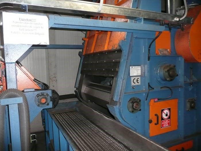
Machine house (blasting space)
The machine house is a welded plate construction with profile steel bracing. The inner surface has manganese wear protection. We place the ABR – 380 type blasting turbine on the top of the machine house. A 5.5 kW, 2800 rpm electric motor with four V-belts drive the turbines. With tilting the motor support you can set the tensioning the V-belts.
The bottom of the machine house is a cone-shaped trough construction. The machine collect here the fallen shot-blasting material and the heavier contaminations. There is a screw conveyor in the conical trough and it conveys the shot-blasting material to the bucket elevator. The drive gear turning the rubber belt is placed on the machine house. The driven, endless rubber belt keeps the bulk parts in continuous movement. There is an aspiration stub on the machine house to aspirate the dust created in the machine house, through which the machine house is connected to the dust aspiration network of the complete machine.
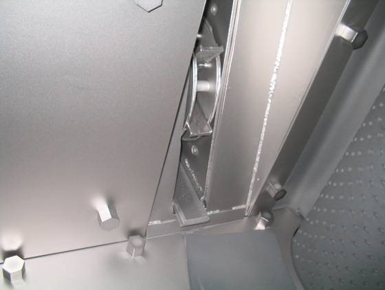
Manganese wear protection
The whole inner surface of the rubber belt shot blasting machine space (machine house) is covered by special wear-resistant manganese plate. The thickness of the plate is 5-8 mm. The wear protection protects the structural units of the machine from the harmful wearing effects of the blasting for a long time. A characteristic feature of the steel with 13% manganese content is that its surface is getting harder and harder because of the hitting-wearing effect of the shots (Hadfield steel). Welding the manganese steel is done by special electrodes which have wear protecting characteristics matching the basic material.
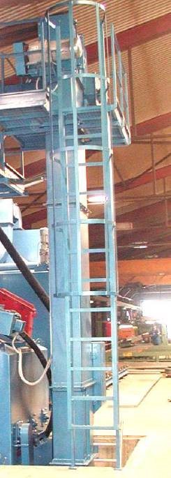
Bucket elevator, with maintenance platform
Its main parts: leg, drag and head. The leg includes the lower drum of the elevator with the bearings. The leg is a welded construction made of bent plate, with connecting frames on its side to connect the cross screw conveyor. The drag is a simple rectangular self-supporting structure. The access hole needed for mounting the belt can be found on it. The head consists of the drum ensuring the drive of the bucket elevator, the chain tensioning structure and the outlet aperture. The head is connected to the drag by bolt connection. The driving drum in the head drives the bucket belt which is used for the tensioning of the belt, too. The buckets are fixed to an endless cloth-insertion rubber belt by bolt connection. Conveying capacity: 4 m3/hour, gear performance: 0.75 kW.
Blasting material cleaning and dosing tank
Cleaning the shots is performed by a suction system, two-step blasting material selecting equipment welded of fine plate. The surface of the steps has rubber covering. You can fid the suction holes on its door. We mount a pipe stub on the back end of the wind sorter. You can connect the butterfly valve regulating the air speed to any end point of it. The dust contamination separated by the wind sorter gets into the dust tank through a rubber hose.
The cleaned shots chute into the dosing buffer tank. The blasting material selected in the blasting material cleaner is collected in the dosing tank. At the bottom of the dosing tank a sector gate ensures the regulation of the shot supply of the blasting heads. We pneumatically operate the sector gate. With the adjusting of the bumpers you set the amount of shot to blast. The blasting material getting into the tank can only flow down through an internal sieve where the bigger size contamination gets tied up which could cause trouble getting into the blasting tank.
Tank volume: 0.25 m3- number of discharging holes: 1 piece. The blasting material flows from the discharge stubs to the blasting turbines through wear-resistant rubber hoses.
Technical details of rubber belt shot blasting machine
Maximum Blasting space, size, capacities:
- Rubber belt width: 950 mm
- Belt disc diameter: 900 mm
- batch volume: 0,27 m3
- weight of batch: 400 kg
- wieght of each part: 7 kg
- Blasting material: steel
The dimensioons of the shoot blasting machine and necessary space to install: accortind to the attached drawing
Blasting method: with impeller wheel manual or automatic method
Necessary staff: 1 person
Blasting material: Steel shoot GP type 0,4-1,2 mm
Blasting materia load: 350 kg
The noise level of the machine: 80-84 dB(A)
Turbines
Number of turbines: 1 pc
Type: ABRD-380
Diameter: 380 mm
Rotation of the turbines: 2800 turn/minute
Scattering power: 130 kg/min/turbine
Electrical power:: 7,5 kW/turbine
Consumption of rubber belt shot blasting machine
Electrical: 14,1 kW
Compressed air
Pressure: 6 bar
Quantity: 6 m3/hour
Dust separator ventillator power: 4500 m3/h
Electrical data
Voltage: 3 x 400 V
Controlling voltageVezérlőfeszültség: 24 V
Frecvency: 50 Hz
Related products
- Ajánlatkérés
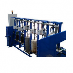
HT 350 – Testing unit for fire extinguishers and cylinders
10 350,00 €On request, it is possible to test also CO2 cartridges
- Ajánlatkérés
FIT50/LOW model- Hydraulic testing unit for liquified low
32 083,00 €Model has been specifically designed to carry out the hydraulic testing of low pressure gas cylinders
- Ajánlatkérés
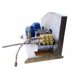
103/D1 filling and recovery pump three pistons transfer pump
5 200,00 €The 103/D1 model is a highly efficient three pistons transfer pump, designed to fill or recover CO2 from cylinders or fire extinguishers. Coud use with gascylinder or bundle
- Ajánlatkérés
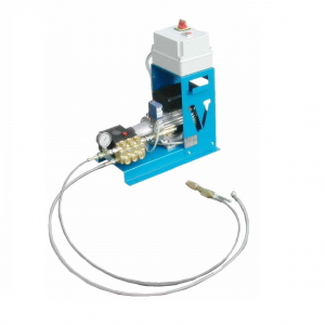
99/D1 transfer pump
2 250,00 €99/D1 unit is mainly suitable for fire-fighting and industrial gas applications and for any other employment requiring to transfer liquid CO2 from standard cylinders to containers or to fire extinguishers with more than 1 kg capacity.